
The Christina River Bridge project is part of a revitalization effort to improve the Wilmington, DE, riverfront. This area had a long history of shipbuilding and other industries but fell into disuse as local industry declined in the decades after World War II.
In recent years, the area has been redeveloped with many commercial, residential, and recreational features, including a Minor League Baseball stadium for the Wilmington Blue Rocks, hotels, apartments, restaurants, and shops. A riverwalk path along the river’s west bank provides pleasurable access to all these amenities, extending from downtown Wilmington to a wildlife preserve to the west.
The new multimodal Christina River Bridge connects the redeveloped riverwalk attractions along the west bank and the current industrial area on the east bank, with the hope of spurring further redevelopment in this area. The bridge will also alleviate traffic congestion and improve mobility and circulation for the riverfront community by introducing additional access to U.S. Route 13, Interstate 495, and Interstate 95.
Geographic Considerations
The new bridge is located at the far western end of the current west bank development. A network of streets within the riverfront development is being extended to improve internal traffic flow and provide additional access points to major highways not currently connected to the riverfront. Initial location studies aimed to make the river crossing as direct as possible, connecting to the logical available termini on both ends. However, this strategy would have placed the bridge too close to developed property; ultimately, a skewed crossing was chosen.
[JPG, 135.02 KB]
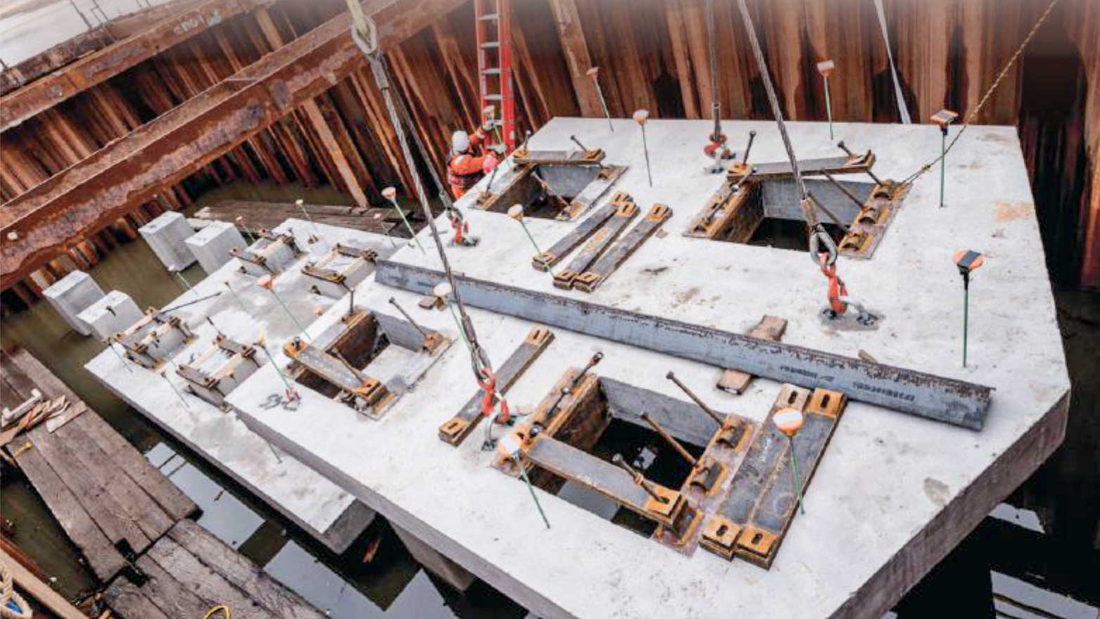
Cofferdam at bridge pier 2 showing 30-in.-square concrete piles and one of the precast concrete bottom soffit form slab segments being placed. (Photo: R.E. Pierson Construction Company)The Christina River is considered navigable in this area of Wilmington, and the navigational clearance requirements dictated a 150-ft-wide channel and a 14-ft-high underclearance. Along the proposed skew, a main span of 180 ft was necessary to provide the required clearance. The Christina River, located close to the Delaware River and Bay, experiences a rather large 5 ft swing in tides between mean high water and mean low water. Stakeholders wanted a low profile for the bridge and roadway to keep the bridge as safe and unobtrusive as possible, simplify multimodal connections to the bridge, and preserve skyline views of downtown Wilmington along the riverwalk.
This combination of geometric constraints posed a challenge for the bridge superstructure design. Initially, a three-span continuous steel girder bridge was investigated and proposed for this site. However, the bridge owner wanted a low-maintenance and durable bridge that would minimize future maintenance and not require painting. Concrete girder options were investigated, but the depth of available standard bulb-tee girders that would provide the 180-ft span and meet the underclearance requirement and tidal range would lead to an undesirably high bridge profile. The solution was to provide a more customized design using fully continuous, spliced pretensioned and post-tensioned concrete bulb-tee girders with haunched segments at the piers. This solution was not the most efficient section, but it met all structural and geometric constraints.
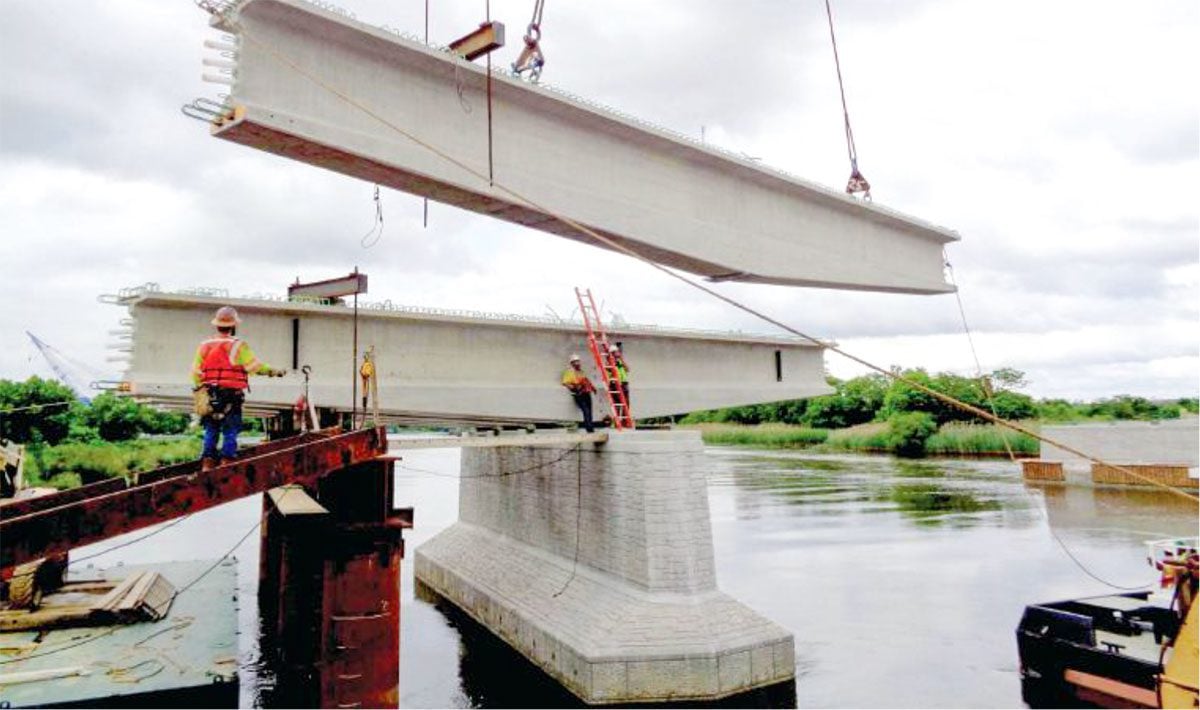
[JPG, 109.04 KB]
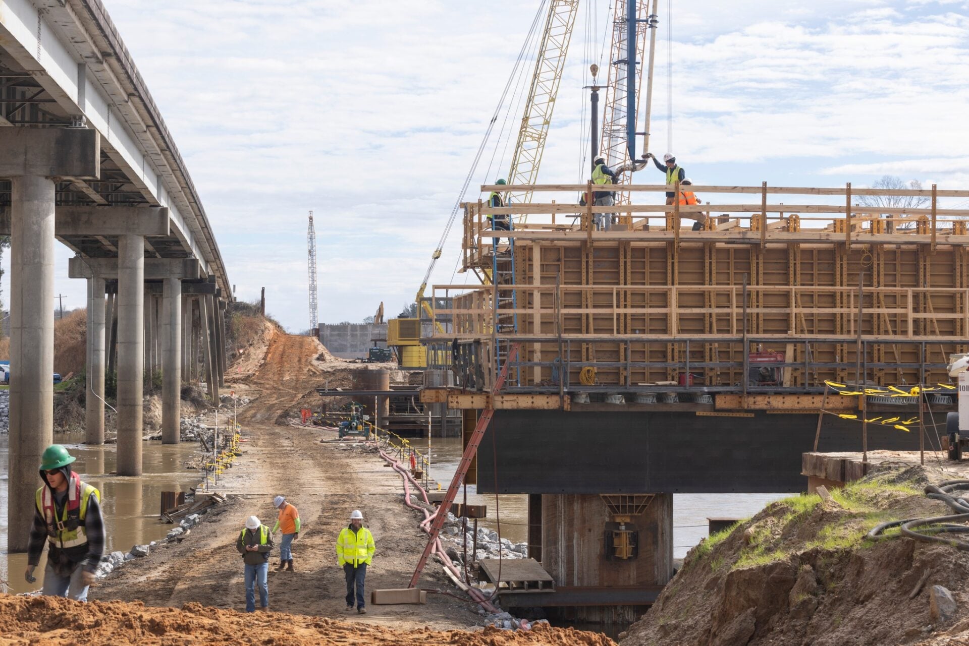
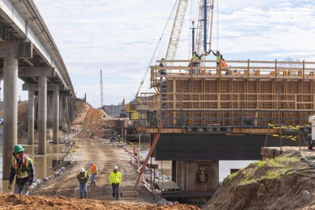
Erection of a haunched pier segment at pier 1. Note the temporary bent in the river being used to temporarily support pier segments. (Photo: R.E. Pierson Construction Company)Project Specifications
The Christina River Bridge comprises three spans (145 ft, 180 ft, 145 ft), for a total length of 470 ft. It is 45 ft wide, carrying two 11-ft-wide lanes of New Sweden Street along with a barrier-separated, 14-ft-wide shared-use path. The bridge alignment is straight but skewed at approximately 65 degrees to the river and on a vertical curve with approach grades of 3.5% and 4.3%.
The typical section has five lines of girders spaced at 9 ft 6 in. with 3 ft 6 in. overhangs. The girders are 5 ft 1 in. deep and are haunched in a straightline taper to a depth of 7 ft 0 in. at each pier. The spliced girders consist of pretensioned precast concrete bulbtee segments that are post-tensioned after splicing. The approach span end segments and the center span drop-in segments were supported by the haunched pier segments during construction prior to post-tensioning.
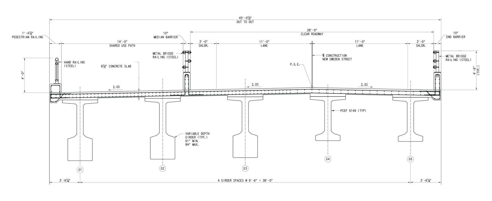
[JPG, 75.82 KB]
The spliced girders consist of pretensioned precast concrete bulb-tee girder segments that are post-tensioned after splicing. They support an 8.5-in.-thick, cast-in-place concrete deck, 4-ft-6-in.-tall roadway barriers with concrete bases and steel railings, and a 4-ft-tall pedestrian railing at the bridge fascia next to the shared-use path. Left side of figure is section at pier; right side is section at midspan and abutments. (Figure: RK&K)The bridge has an 8.5-in.-thick, cast-in-place concrete deck. The roadway barriers are 4 ft 6 in. high with concrete bases and a steel railing, and the pedestrian railing for the shared-use path is 4 ft high with a concrete curb section and steel railing.
The project also includes approximately 600 linear ft of retaining walls on the roadway approaches to the bridge. Mechanically stabilized earth walls are used on the east approach and cast-in-place concrete walls on the west approach. A pedestrian underpass beneath the west approach embankment provides connectivity along the existing riverwalk on the west bank of the Christina River; a set of cast-in-place concrete stairs connects the multimodal path on the bridge and the riverwalk below. The underpass has a cast-in-place concrete frame, about 50 ft long and 45 ft wide, with an arching ceiling, full lighting, and panels for future displays of artwork.
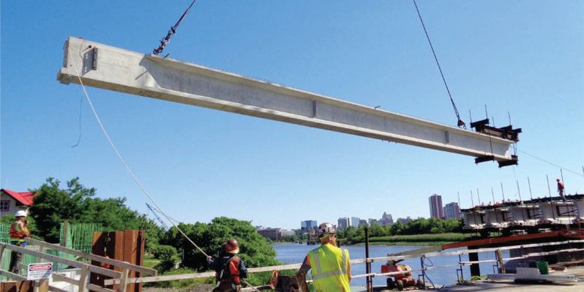
[JPG, 92.54 KB]
Erection of an end girder segment in span 1 from the working platform. Note the preinstalled strongback at the pier end of the segment and the end block for post-tensioning anchorages at the abutment end of the segment. The end detail of the girders at the abutments was modified at the request of the precaster because, in their experience, the small piece of the top flange that extends beyond the end block has a tendency to crack at the interface. (Photo: R.E. Pierson Construction Company)Aesthetic Considerations
Given this bridge’s prominent location as a focal point within the riverwalk development, the aesthetics of the structures were deemed quite important. As noted, the geometrics of the bridge (low profile, convenient access, and unencumbered views of the downtown skyline) were critical elements in the bridge’s siting and design. As the design evolved, other elements were added to enhance the aesthetics. Bridge piers were shaped and contoured. Abutments and retaining walls were developed in tandem to ensure a coordinated appearance, especially in the transition areas. Concrete surfaces on the piers, abutments, and walls received stone formliner treatments and were stained for maximum, but subtle, effect. The multimodal underpass, stairway, and adjacent walls were all detailed and treated to coordinate with the bridge detailing, presenting a uniform, pleasing appearance.
Geotechnical Challenges
The site was contaminated with heavy metals, a legacy of past industrial use. The west approach for the bridge is located over an old buried stream/canal. The subsurface soils consisted of a thin crust of fill underlain by layers of very soft, highly plastic silt and clay with bedrock encountered approximately 100 ft below existing grade. Geotechnical design challenges included global stability, long-term settlement, and down-drag on the bridge foundations.
[JPG, 63.54 KB]
With all concrete girder segments erected, strongbacks temporarily support girder segments until closure pours and post-tensioning are completed. (Photo: R.E. Pierson Construction Company)A variety of structural and geotechnical options were studied during design. The proposed geotechnical treatments included expanded polystyrene and low-density, controlled low-strength material as backfill for the retaining walls along the west approach, soil modification using deep-mixing methods along the east approach adjacent to the bridge, and surcharge and quarantine of the eastern-most portion of the embankment. The contractor eventually proposed using controlled-modulus columns in lieu of deep-mixing methods to save time, and this solution was accepted and incorporated into the structure. The bridge and all structures within the project are founded on driven 24-in.- and 30-in.-square prestressed concrete piles.
Construction
Bridge design was completed in the fall of 2016, and the bridge project was let for bidding in December. The approach roadway work was omitted from the contract for the bridge portion of the project because of challenges with the right-of-way. Separate contracts allowed the bridge construction to begin while the right-of-way issues were resolved. The timing of the bridge and roadway contracts was coordinated with the intent that both projects would be completed at the same time; however, delays to the roadway contract have caused the overall project completion to extend into 2020.
Bids were opened in January 2017, with a low bid of $28.4 million compared with the engineer’s estimate of $18.8 million. Design changes and value engineering proposals brought the cost down to approximately $27 million. Construction began in summer 2017.
In the initial stages of construction, the contractor decided to use temporary work platforms built out into the river adjacent to the bridge end spans. This provided good access for equipment and material supply out to the river, where floating cranes and other equipment would be positioned.
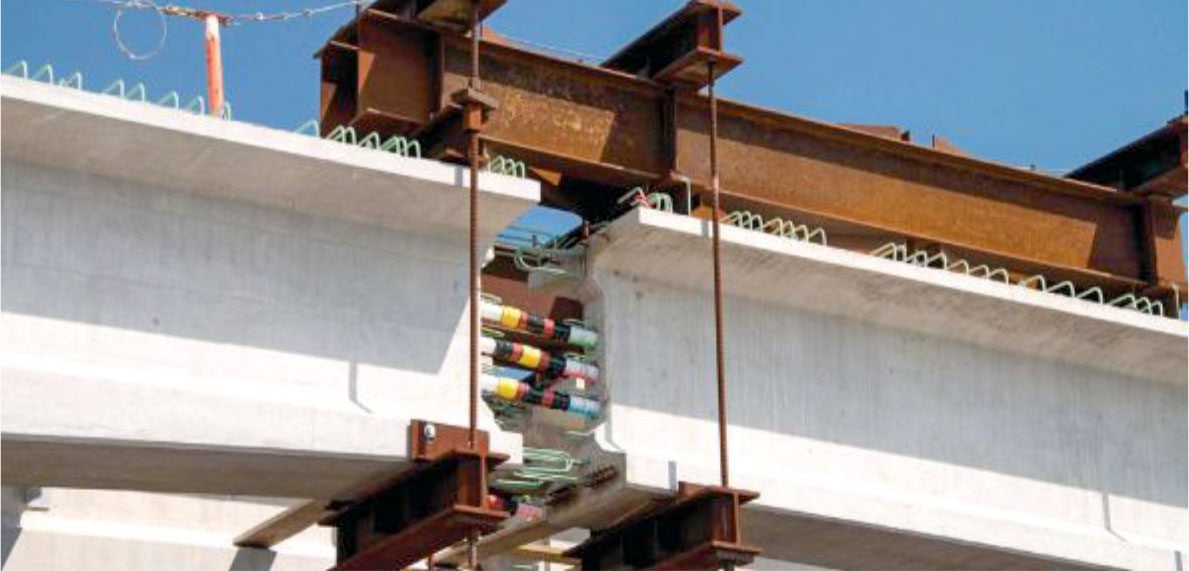
[JPG, 79.24 KB]
A close-up view of the strongback supporting the end segments on the pier segments before the closure pour. Spliced post-tensioning ducts are visible in the 24-in.-wide joint. Stirrups and other closure pour reinforcement had not yet been installed. (Photo: R.E. Pierson Construction Company)The contractor also decided to install temporary bents within the footprints of the two end spans on the landward side of the two piers. These provided stable platforms to support the precast concrete pier segments until the closure pours and post-tensioning were completed.
Cofferdams were used to build the foundations for the two piers in lieu of floating in formwork boxes. Within the cofferdams, the contractor used precast concrete soffit slabs to serve as a template for the pile driving and as bottom formwork for the pier footings. Finally, the contractor drove two temporary test piles within the end-span footprint to ensure drivability of the proposed prestressed concrete piles.
The post-tensioned concrete girders are designed as fully continuous for deck dead load, superimposed dead load, and live load. The girder segments were cast using 9000-psi concrete with seven-wire, low-relaxation, 0.6-in.-diameter strands. Minimum compressive strength at transfer was 6800 psi. Each girder had three post-tensioning tendons with twelve 0.6-in.-diameter strands in a 33∕8-in.-diameter corrugated plastic duct. A tensioning force of 527 kip was specified for each of the three draped tendons in each continuous girder.
The contractor followed the superstructure sequence of construction detailed in the plans for the erection and splicing of the precast concrete girder segments. Once the piers and abutments were completed, pier girder segments were erected at the piers using the previously installed temporary bents for two-point support. These girder segments were temporarily braced while the concrete pier diaphragms were cast and permanent galvanized steel diaphragms were connected.
Next, the end girder segments were erected with strongback connections preinstalled at the pier ends. The strongbacks secured the ends of the girder segments, providing a 24-in.-wide closure pour in which ducts were spliced. Then bracing was installed, and geometry and alignment checks were made.
The midspan drop-in segments were erected next, again with strongbacks preinstalled at both ends. Alignment, grade, and spacing were checked and bracing was installed.
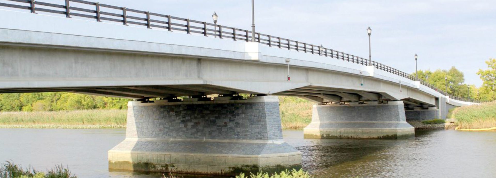
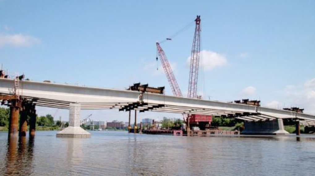
[JPG, 162.46 KB]
View of the completed bridge looking east. The piers were enhanced using formliners and staining. (Photo: Robert J. Healy, RK&K)After all superstructure segments had been erected, ducts were spliced and closure pours were cast. When the closure pours reached the specified compressive strength of 6500 psi, post-tensioning strands were installed and the tendons tensioned in a specified sequence. After acceptance, tendons were grouted and, following a minimum of three days, strongbacks and temporary supports were removed and end diaphragms cast. Upon completion of these items, the bridge deck, barriers, railings, lighting, and all other appurtenances and structures were constructed, including the retaining walls, underpass, and stairway.
Conclusion
The bridge and adjoining structures are now substantially complete and are awaiting the completion of the approach roadways. The entire facility is expected to be finished and operational in 2020.
You might also be interested in:
Blog

Value Engineering: A Strategic Advantage in Modern Infrastructure Delivery